|
AUTOZINE TECHNICAL SCHOOL
Turbocharging Overview
Basic Theory The advantage of turbocharging is obvious - instead of wasting thermal energy through exhaust, we can make use of such energy to increase engine power. By directing exhaust gas to drive a turbine, which drives another turbine to pump fresh air into the combustion chambers at a pressure higher than normal atmosphere, a small capacity engine can deliver power comparable to much bigger opponents. For example, if a 2.0-litre turbocharged engine works at 1.5 bar boost pressure, it actually equals to a 3.0-litre naturally aspirated engine. As a result, the size and weight of engine can be reduced, thus leads to better acceleration, handling and braking, though fuel consumption is not necessarily better. Problems - Turbo Lag Turbocharging was first introduced to production car by General Motors in 1962, using on Chevrolet Corvair. That car had very bad reputation for poor low-speed output and excessive turbo lag which made fluent driving impossible. Turbo Lag was the biggest problem preventing the early turbo cars from being accepted as practical. Although turbocharging had been extensively and successfully used in motor racing - started from BMW 2002 turbo and then spread to endurance racing and eventually F1 cars - road cars always require a more user-friendly power delivery. Contemporary turbines were large and heavy, thus could not start spinning until about 3,500 rpm. As a result, low-speed output remained weak. Moreover, since contemporary turbocharging required compression ratio to be decreased to about 6.5:1 in order to avoid overheating to cylinder heads, the pre-charged output was even weaker than a normally-aspirated engine of the same capacity ! 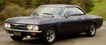 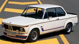 The earliest turbocharged production cars: Chevrolet Corvair Turbo and BMW 2002 Turbo Turbo lag could cause trouble in daily driving. Before the turbo intervenes, the car performs ordinarily. Open throttle wide and raise the engine rev, counting from 1, 2, 3, 4 .... suddenly the power surge at 3,500 rpm and the car becomes a wild beast. On wet surfaces or tight bends this might result in wheel spin or even lost of control. In the presence of turbo lag, it is very difficult to drive a car fluently. Besides, turbo lag ruins the refinement of a car very much. Floor the throttle cannot result in instant power rise expected by the driver - all reactions appear several seconds later, no matter acceleration or back off. You can imagine how difficult to drive fast in urban area or twisted roads. Porsche's solution to turbo lag
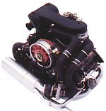
Intercooler The air supplied by turbocharger could be as hot as 120-150ºC. This is owing to two reasons: 1) Compression of air leads to increased temperature; 2) Heat from the hot exhaust gas conducts to the compressor side. As hot air has lower density than cold air, the amount (mass) of air entering the combustion chambers is actually reduced, leading to lower volumetric efficiency hence lower output. Moreover, the higher temperature attained by the cylinder head may cause knocking or even damage to the head itself, so compression ratio has to be lowered to compensate. In 1978, the 3.3-litre version of 911 Turbo introduced intercooler to solve this problem. Located between the compressor and the engine, the air-cooled intercooler reduced the air temperature by 50-60ºC, improving volumetric efficiency and allowing the compression ratio to be raised. Of course, higher compression led to improved low-speed output.
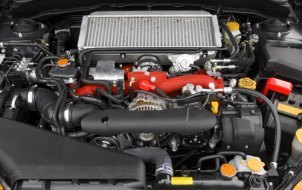
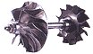
Today, intercooler is virtually standard on all turbocharged cars. They are usually mounted behind the front bumper intakes to take advantage of cold air. Some older cars have intercoolers installed above the engine and breath through a bonnet-mounted scoop. However, such designs are no longer possible as new pedestrian safety regulations in Europe require more clearance between the engine and bonnet. The only exception is Subaru's boxer engine as it is inherently low enough. Continuous development During the 1980s, turbocharging continued evolving for better road manner. As materials and production technology progressed, the weight and inertia of turbines were significantly reduced, speeding up response and reducing turbo lag a lot. To handle the tremendous heat in exhaust flow, turbines are mostly made of stainless steel or ceramic (the latter is especially favoured by the Japanese IHI). Occasionally there are some cars employ titanium turbines, which are even lighter but very expensive.
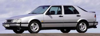
Another area of improvement was boost control. The early turbo engines employed mechanical wastegate to avoid over-pressuring the combustion chambers. Without wastegate, the boost pressure would be proportional to the engine speed (because the speed of turbine depends on the amount of exhaust flow, hence the engine rev). At high rev, the pressure would be so high that cause over-stress and over-heat to the combustion chambers, thus may damage the engine. Wastegate is a valve added to the exhaust turbine housing. Whenever the gas pressure exceeds a default value, it opens and releases the boost pressure. The introduction of electronic boost control in the late 1980s took a great step forward from mechanical wastegates. While a wastegate just sets the upper limit of boost pressure, electronic boost control governs the boost pressure throughout the whole rev range. For example, it may limit the boost to 1.4 bar for below 3,000 rpm, then 1.6 bar for 3,000 to 4,500 rpm and then 1.8 bar for above 4,500 rpm. This helps achieving a linear power delivery and contributes to driving refinement. Basically, electronic boost control is just a wastegate activated by engine management system. Light Pressure Turbo Saab was a leader in turbocharging history. After producing the first successful turbocharged mass production car (99 Turbo) and the first combination of turbo and 4-valve engine (9000 turbo), it pioneered light pressure turbocharging in 1992. The Saab 9000 Turbo Ecopower produced 170 horsepower from a 2.3-liter engine, 30 hp less than the standard turbocharged engine and only 20 hp more than its naturally aspirated version. It ran a max boost pressure of only 0.4 bar. While this seemed to be a waste of materials, Saab saw LPT as a means to improve drivability without the drawback of conventional turbocharging. Despite of lower peak power, an LPT engine remains to be strong in torque delivery thus aids acceleration. Most important, it has very much better drivability due to substantially reduced turbo lag. Throttle response is nearly instant. Besides, Saab proved that the better torque curve enables taller gearing, thus actually delivers better fuel economy than a normally aspirated engine of the same size !
LPT is attractive to car makers. As modern family cars and luxury cars get heavier and heavier, LPT can provide the extra torque they need without resorting to larger engines. This mean they can keep the cost-effective four-cylinder engines rather than upgrading to six-cylinders. The refined manner of LPT, in addition to the use of twin-balancer shafts and other NVH suppression know-how, makes four-cylinder engines viable substitutions to six-cylinder power plants. The trend of LPT gets even more obvious in the new millenium as the world chases green motoring. Today, many cars offer a small turbo engine with 2 levels of power, a light pressure turbo for the majority who care more about costs and fuel consumption, and a higher boost version for those seeking better performance. With this arrangement, car makers no longer needs to build several engines with different capacities. A different spec. turbo or even just a different ECU will do the job, hence saving a great deal of R&D and tooling costs. Variable Turbine Geometry (VTG) Variable Turbine Geometry (VTG) technology is commonly used in turbo diesel engines. It is primarily used to reduce turbo lag at low engine speed, but it is also useful to introduce EGR (Exhaust Gas Recirculation) to reduce emission in diesel engines. Here we concentrate on the former advantage. Ordinary turbochargers cannot escape from turbo lag because at low engine rpm the exhaust gas flow is not strong enough to bring the turbine up to operating speed. This problem is especially serious to modern diesel engines, because they tend to use big turbos to compensate for their lack of efficiency. A VTG turbocharger is capable to alter the direction of exhaust gas flow to optimize turbine response. It incorporates many movable vanes inside the turbine housing to guide the exhaust flow towards the turbine. An actuator can adjust the angle of these vanes, in turn vary the angle of exhaust flow. See the following illustrations: At low rpm: The vanes are partially closed, reducing the area hence accelerating the exhaust gas towards the turbine. Moreover, the exhaust flow hits the turbine blades at right angle. Both makes the turbine spin faster. 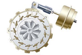  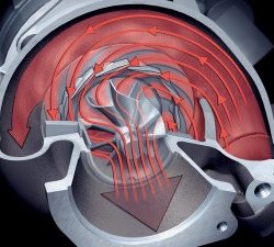 At high rpm: At high rpm the exhaust flow is strong enough. The vanes are fully opened to take advantage of the high exhaust flow. This also release the exhaust pressure in the turbocharger, saving the need of wastegate. 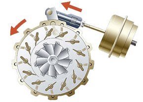  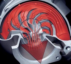 VTG on gasoline engines Although VTG technology is extensively used in diesel engines, it is very much ignored in gasoline engines. This is because the exhaust gas of gasoline engines could reach up to 950°C, versus 700-800°C in diesel engines. Ordinary materials and constructions are difficult to withstand such temperature reliably. In 1989, Honda produced a handful of Legend Wing Turbo, which employed a variable geometry turbocharger developed by itself. Its variable vanes ("wings") were made of a special heat-resisting alloy, Inconel. Nevertheless, the experimental production run was never followed by mass production. In the next one and a half decade Honda simply gave up turbocharging in all its petrol cars. In the same year, Garrett produced a VTG turbocharger for use in the limited production Shelby CSX, a car derived from Dodge Shadow. However, only 500 cars were produced. Neither Chrysler group nor any other car makers would follow its footprints. As compression ratio increases, modern gasoline engines have exhaust temperature higher and higher. Experts estimate it could exceed 1000°C in the foreseeing future. Perhaps this is why VTG technology for gasoline engines never went into mass production. In 2006, BorgWarner finally developed a VTG turbocharger for use in Porsche 911 (997) Turbo. Both firms refused to reveal the technical details, but said it employed "temperature-resistant materials derived from aerospace technology". Hopefully the technology breakthrough will finally bring VTG turbochargers into mass production gasoline engines. Variable-Volume Turbine by Koenigsegg Koenigsegg introduced a so-called "variable geometry twin-turbo" on its One:1 supercar in 2014. It caught me a surprise as until now only Porsche and its partner BorgWarner managed to put VTG technology in gasoline production cars (see above). BorgWarner's technology employs movable vanes made of special alloy to resist the extreme heat attained in gasoline turbo engines. Koenigsegg is not in a position to develop sophisticated materials, of course, but it found a simpler yet not necessarily poorer solution. The problem is, in Koenigsegg's fashion it did not reveal the technical details. Christian von Koenigsegg just explained its theory briefly in a video without showing its internal construction. Fortunately, I found its patent filing in the US Patent and Trademark Office, thanks to Google Patents. Having spent a night studying it, I can proudly present to our readers the world's first and exclusive insight into this technology. Strictly speaking, Koenigsegg's design is not "variable geometry turbine" because it does not have moving vanes to alter the direction of air flow. Instead, it employs a special turbine housing which provides variable volume to optimize efficiency at different engine speed. Therefore, I would rather call it "variable-volume turbine". Before seeing how it works, let's recall why we need VTG turbos. A turbocharger with large volume turbine housing can let a lot of exhaust gas flows through, thus it works efficiently at high engine speed. However, at low rpm the exhaust flow could be so slow that fails to spool up the turbo, thus causing turbo lag. In contrast, a turbo with small turbine housing speeds up the exhaust flow thus works responsively at low rpm, but at higher rpm the flow rate is restricted by the size of the housing, causing more back-pressure and reducing output. Such contradiction can be solved by using variable geometry turbine, but it might be as well solved if we can make the volume of turbine housing variable. That's the thinking behind Koenigsegg. Let's see the illustration below: 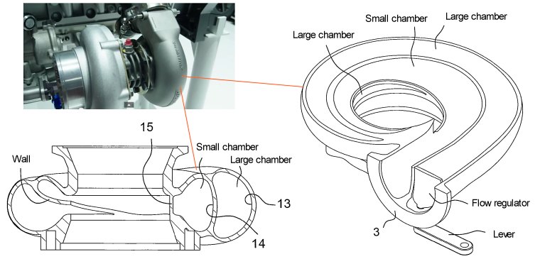 Surprisingly, the construction is pretty simple. Its turbine housing is actually similar to twin-scroll turbos, with a wall separating the housing into 2 chambers. However, where the chambers in twin-scroll turbo are equal in size, here the outer one is larger than the inner one (see the cross section drawing). At low rpm, the exhaust gas flows through only the smaller chamber, so it can spool up the turbo more quickly. At higher rpm, a flow regulator valve - actuated by a lever - opens the gas flow also to the large volume chamber, thus it allows large amount of gas to the turbine without causing extra back-pressure. Look deeper into the design and you will find it is not as simple as first appeared. The 2 chambers and separating wall are actually twisted. If you cut the cross-section at different locations along the turbine housing, you will find their shapes vary: 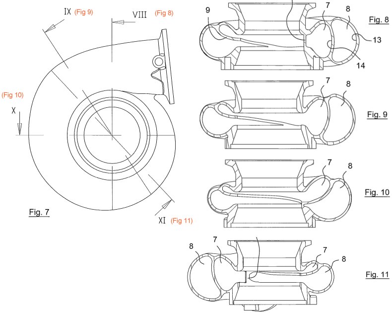 What can you see? For the smaller chamber, the exhaust flow is exposed to the turbine blades immediately after it has entered the chamber (Fig 8). Moreover, as it flows further, the chamber gets narrower and eventually vanishes just after the cross-section X. This means the exhaust gas from this chamber hits mostly the first quarter of the turbine wheel, by that time the gas flow has yet to gather swirling effect. This, in addition to the fact that the gas flow is relatively fast in this smaller chamber, means the flow hits the turbine blades at right angle, optimizing the effect for turbo spool up. The situation at the larger chamber is on the contrary. Exhaust gas meets the turbine wheel much later. As it travels further along the chamber, the chamber exposes it increasingly more to the turbine wheel. This mean the exhaust gas from this chamber drives mostly the second and third quarter of the turbine wheel. (BTW, it is nice to see the 2 separating exhaut flows act at different sections of the turbine wheel so that turbulence or interference can be avoided) As this flow travels much longer in the curvy chamber, swirling effect is built up and, in addition to the slower flow speed at this larger chamber, the gas flow hits the turbine blades at faster angles (i.e. direction of flow is close to radial). This has the same effect as a VTG turbine operating at high rpm setting. Because of the lack of moving vanes, the Koenigsegg design is far less sophisticated than VTG turbos. Its flow regulator valve can be easily manufactured. It does not even need to seal the chamber inlet completely, because the shorter length of small chamber tends to attract more exhaust gas than the longer large chamber until back pressure is built up at higher rev. In other words, even without the flow regulator valve the variable volume feature would work reasonably well. The only sophisticated part of the Koenigsegg design is the spiral turbine housing, whose twisted shape cannot be made with conventional casting process. Koenigsegg uses 3D printing to produce the housing out of steel and titanium. This could be very expensive and infeasible for mass production, but it suits perfectly the case of Koenigsegg. |
||||||||||
| Copyright© 1997-2015 by Mark Wan @ AutoZine |